Company name: Beijing Fengyu Huayuan Instrument And Meter Co., Ltd
24-hour service Tel: 13910924471
Tel: 010-65264544
Holiday duty Tel.: 13910924471
QQ:99133400
Company address: No. 20, Shengshun street, Daxing District, Beijing
Postal Code: 100078
Email: yufenghuayuan@126.com
website: http://www.longog.com
Contact: Mr. Zhang
1. System function overview
The system is controlled by an industrial computer, which can test the fan speed, torque, vibration, noise, temperature and humidity, current, power, rated point air pressure measurement, rated point air volume measurement, output power PS, efficiency Eff, maximum air pressure and Various characteristic curve tests. The characteristic curve test is carried out on the test bench. All project test procedures are collected and tested by the computer, and the test results are displayed.
The computer system adopts WIN7/WIN8 operating system with beautiful man-machine interface, which can collect, record, store and display test data and results of various items, print test data and characteristic curves, and provide convenient operation, flexible adjustment, and intuitive and clear man-machine interface Computer software.
This system can use a fully automatic way to control the inlet/outlet air volume equipment, so that the tested fan can work at a specified pressure point, or the tested fan can work at a specified pressure range.
This system can control variable frequency motors and frequency converters for speed regulation tests, and has the following advantages:
1. By controlling the compensating fan and overcoming the wind resistance of the test air pipe, the extreme performance of the fan can be tested.
2. Change the speed of the measured fan to obtain the complete performance curve of the fan at different speeds and different wind resistances.
2. Production standards:
1. This system is designed and manufactured according to GB/T1236.
2. This system uses the orifice plate method for measurement, and the orifice plate measurement system is manufactured according to GBGB/T2624-2006.
3, system composition
This system is composed of a central control computer and a measurement system. During the test, the intelligent instrument transmits data such as pressure, temperature, speed, torque, and power to the computer, and performs data processing through the integrated operating software of the system. The measurement parameters can be controlled automatically or manually, and the fan curve diagram will be produced.
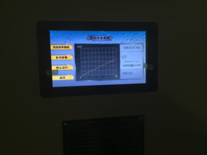
The various parts of the system communicate through the advanced CAN bus. The randomly installed touch screen can display the measurement data and results in real time. The system can work independently from the computer.
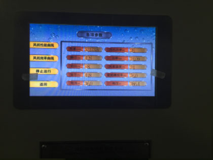
4, measurement parameters and range
1. Pressure: 0-4000pa Accuracy: 1%
2. Flow rate: 160000m3/h Accuracy: 1%
3. Temperature: -50-150 degrees, accuracy: 0.5 degrees
4. Speed measurement: 0-4000rpm Accuracy: 1rpm (optional)
5. Torque: 0-50N/m Accuracy: 0.1N/m (optional)
6. Power: 0-45KW Accuracy: 1%
7. Vibration test range: 0~100mm/s (vibration speed) Accuracy: 1.5% (optional)
9. Master touch LCD screen 10-inch industrial-grade resistive screen
10. Noise test range: 30-130dB accuracy: ±1.5dB (optional)
11. Fan efficiency: 0-100% accuracy: 1.5%
5, main equipment configuration
1. One industrial computer, including host and display (optional)
2. Air chamber and duct drawings: including detailed information on the inlet and outlet side test section, common section, measuring orifice plate and other components, processing technology, control tolerances, and sensor installation location and other detailed information. (Specific consultation on specific ducts)
4. A set of test system hardware, see the table below for details. With touch screen display operation panel.
5. A set of test software, with various types of test ducts.
6. Test system host
7. System control cabinet (optional inverter with power required by users-optional accessories).
6, detailed equipment configuration
|
Serial number |
Equipment name | Model specification | Quantity | Unit | Remark |
| 1 | System control cabinet | Cabinet | 1 | Tower | Place the instrument and the electrical control part in the system |
| 3 | Electric energy detection system | YF150 | 1 | handful | Test three items of current, voltage, active power, and reactive power |
| 4 | Torque tachometer | YF180 | 1 | Test fan speed, torque, shaft power (optional) | |
| 5 | Pressure Sensor | Integrated | 6 | path | Outlet static pressure test |
| Dynamic pressure test | |||||
| Imported static pressure test | |||||
| Supporting use, test air volume, dynamic and static pressure | |||||
| 6 | Temperature Sensor | Integrated PT1000 | 1 | path | Test multi-channel temperature |
| 7 | Revolution counter | Separate tachometer | 1 | path | Effective speed |
| 8 | Vibration measuring instrument | 1 | Tower | Motor vibration test customer option | |
| 9 | Sound level meter | 1 | Individual | Noise measurement (optional) | |
| 10 | Hygrometer | System integration | 1 | path | Site humidity |
| 11 | The entire central control system cabinet | 1 | Jacketed | 1.8*0.8*0.4m | |
| 12 | 10-inch touch industrial-grade LCD screen | System integration | 1 | Jacketed | Touch control the entire system operation |
| 13 | Total test system | System integration | 1 | Jacketed | Customized according to customer's measured fan parameters |
| 14 | Testing software | 1 | Jacketed | Dedicated test software for wind turbines, including a variety of test duct options |
|
| 15 | Freight | 1 | Times | Specific negotiation according to customer requirements | |
| 16 | Frequency converter | 1 | Jacketed | According to the power selection inverter (optional) | |
| 17 | Inverter fan | 1 | Jacketed | Prepared by customer | |
| 18 | Other auxiliary accessories | 1 | batch | Prepared by customer | |
| 19 | Field cables and wires | 1 | batch | Prepared by customer | |
| 20 | Test Certificate of Metrology Institute | 1 | Jacketed | Test Certificate of Hebei Metrology Institute |
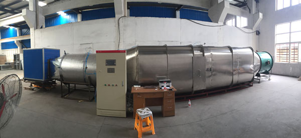
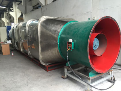
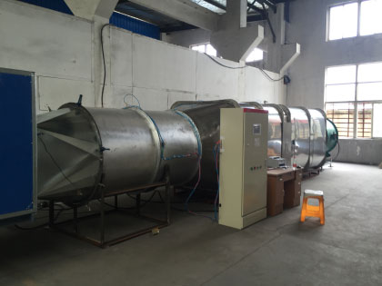
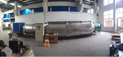
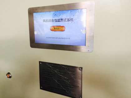
System site photos
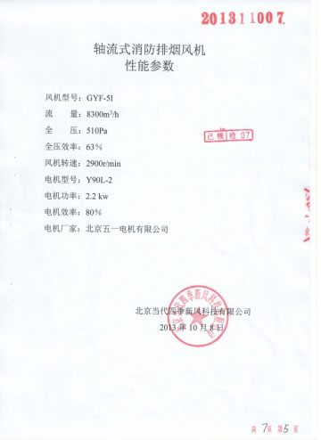
Standard fire fan and test report provided by Tianjin Fire Research Institute
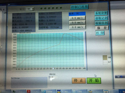
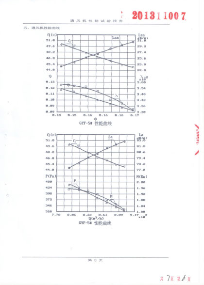
Display data comparison with the tested standard fan curve graph
 ©2021 BEIJING FENGYU HUAYUAN INSTRUMENT AND METER CO.,LTD. All rights reserved
  京公网安备 11011502005088号
 English
 简体中文
简体中文